Overview #
Video Window components #
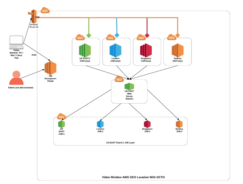
- Shard Server
- WebRTC compatible JavaScript application that uses Media Videobridge to provide high quality, scalable video conferences. Build upon React and React Native.
- Server-side focus component used in Video Window conferences that manages media sessions and acts as load balancer between each of the participants and the Media Bridges.
- Prosody – XMPP server used for signaling
- Media Bridge “JVB” – WebRTC compatible server designed to route video streams amongst participants in a conference.
- HAProxy, used as Load balancer for high availability and Geo Location support.
- Laravel based management portal application used for authentication and authorization of clients and used as well to implement some APIs required by the VW Desktop and Mobile Apps.
XMPP Signaling #
XMPP is a communications protocol for message-oriented middleware based on XML. XMPP provides a general framework for messaging across a network. It is pretty much the same piece of technology as the one Google uses for Hangouts. XMPP stands for Extensible Messaging and Presence Protocol (XMPP) which is an open XML technology for real-time communication, which powers a wide range of applications including instant messaging, presence and collaboration.
To understand what this really means, let’s go on a journey from P back to X :
- P — Protocol
- XMPP is a protocol; a set of standards that allows systems to talk to each other. XMPP is used widely across the web, but is often unadvertised. The protocol (or standards) are looked after by the XSF (link).
- P — Presence
- The presence indicator tells the servers that you are online / offline / busy. In technical terms, presence determines the state of an XMPP entity; in layman terms, whether you are there and ready to receive messages or not.
- M — Messaging
- The ‘messaging’ part of XMPP is the ‘piece’ you see; the Instant Message (IM) sent between clients. XMPP has been designed to send all messages in real-time using a very efficient push mechanism; whereas existing web based mechanisms often make many unnecessary requests introducing network load, and are consequently not real-time.
- X — eXtensible
- Defined in an open standard and using an open systems approach of development and application, XMPP is designed to be extensible. In other words, it has been designed to grow and accommodate changes.
WebRTC signaling refers to the process of setting up, controlling, and terminating a communication session. In order for two endpoints to begin talking to one another, three types of information must be exchanged:
- Session control information determines when to initialize, close, and modify communications sessions. Session control messages are also used in error reporting.
- Network Data reveals where endpoints are located on the Internet (IP address and port) so that participants can communicate to each other.
- Media Data is required to determine the codecs and media types. If endpoints attempting to start a communications session have differing resolution and codec configurations, then a successful conversation is unlikely. Signaling that exchanges media configuration information between peers occurs by using an offer and answer in the Session Description Protocol (SDP) format.
In a nutshell, WebRTC signaling allows for users to exchange metadata to coordinate communication.
RTCPeerConnection is the API Video Window uses to establish peer connections and transfe audio and video media. In order for the connection to work, RTCPeerConnection must acquire local media conditions (resolution and codec capabilities, for instance) for metadata, and gather possible network addresses for the application’s host. The signaling mechanism for passing this crucial information back and forth is not built into the WebRTC API.
The WebRTC specification includes APIs for communicating with an ICE (Internet Connectivity Establishment) Server, but the signaling component is not part of it. Signaling is needed in order for two peers to share how they should connect. Usually this is solved through a regular HTTP-based Web API (i.e., a REST service or other RPC mechanism) where web applications can relay the necessary information before the peer connection is initiated.
The following code snippet shows how this fictitious signaling service can be used to send and
receive messages asynchronously. This will be used in the remaining examples in this guide where necessary.
// Set up an asynchronous communication channel that will be used during the peer connection setup const signalingChannel = new SignalingChannel(remoteClientId);signalingChannel.addEventListener(‘message’, message => {// New message from remote client received});
// Send an asynchronous message to the remote client signalingChannel.send(‘Hello!’);
Each peer connection is handled by a RTCPeerConnection object. The constructor for this class takes a single RTCConfiguration object as its parameter. This object defines how the peer connection is set up and should contain information about the ICE servers to use.
Once the RTCPeerConnection is created we need to create an SDP offer or answer, depending on if we are the calling peer or receiving peer. Once the SDP offer or answer is created, it must be sent to the remote peer through a different channel. Passing SDP objects to remote peers is called signaling and is not covered by the WebRTC specification.
To initiate the peer connection setup from the calling side, we create a RTCPeerConnection object and then call createOffer() to create a RTCSessionDescription object. This session description is set as the local description using setLocalDescription() and is then sent over our signaling channel to the receiving side. We also set up a listener to our signaling channel for when an answer to our offered session description is received from the receiving side.
async function makeCall() {
const configuration = {‘iceServers’: [{‘urls’: ‘stun:stun.l.google.com:19302’}]}
const peerConnection = new RTCPeerConnection(configuration);
signalingChannel.addEventListener(‘message’, async message => {
if (message.answer) {
const remoteDesc = new RTCSessionDescription(message.answer);
await peerConnection.setRemoteDescription(remoteDesc);
}
});
const offer = await peerConnection.createOffer();
await peerConnection.setLocalDescription(offer);signalingChannel.send({‘offer’: offer});
}
On the receiving side, we wait for an incoming offer before we create our RTCPeerConnection instance. Once that is done we set the received offer using setRemoteDescription(). Next, we call createAnswer() to create an answer to the received offer. This answer is set as the local description using setLocalDescription() and then sent to the calling side over our signaling server.
const peerConnection = new RTCPeerConnection(configuration);
signalingChannel.addEventListener(‘message’, async message => {
if (message.offer) {
peerConnection.setRemoteDescription(new RTCSessionDescription(message.offer));
const answer = await peerConnection.createAnswer();
await peerConnection.setLocalDescription(answer);
signalingChannel.send({‘answer’: answer});
}
});
Before two peers can communicate using WebRTC, they need to exchange connectivity information. Since the network conditions can vary depending on a number of factors, an external service is usually used for discovering the possible candidates for connecting to a peer.
This service is called ICE and is using either a STUN or a TURN server. STUN stands for Session Traversal Utilities for NAT, and is usually used indirectly in most WebRTC applications. TURN (Traversal Using Relay NAT) is the more advanced solution that incorporates the STUN protocols and most commercial WebRTC based services use a TURN server for establishing connections between peers. The WebRTC API supports both STUN and TURN directly, and it is gathered under the more complete term Internet Connectivity Establishment. When creating a WebRTC connection, we usually provide one or several ICE servers in the configuration for the RTCPeerConnection object.
Once a RTCPeerConnection object is created, the underlying framework uses the provided ICE servers to gather candidates for connectivity establishment (ICE candidates). The event icegatheringstatechange on RTCPeerConnection signals in what state the ICE gathering is (new, gathering or complete).
While it is possible for a peer to wait until the ICE gathering is complete, it is usually much more efficient to use a “trickle ice” technique and transmit each ICE candidate to the remote peer as it gets discovered. This will significantly reduce the setup time for the peer connectivity and allow a video call to get started with less delays.
Once ICE candidates are being received, we should expect the state for our peer connection will eventually change to a connected state. To detect this, we add a listener to our RTCPeerConnection where we listen for connectionstatechange events.
// Listen for connectionstatechange on the local RTCPeerConnection
peerConnection.addEventListener(‘connectionstatechange’, event => {
if (peerConnection.connectionState === ‘connected’) {
// Peers connected!
}
});
Turn Server : For most WebRTC applications to function a server is required for relaying the traffic between peers, since a direct socket is often not possible between the clients (unless they reside on the same local network). The common way to solve this is by using a TURN server. The term stands for Traversal Using Relay NAT, and it is a protocol for relaying network traffic.
Video Window uses a self-hosted open-source implementation of COTURN project as Turn and Stun server.


